

Degreasing Roll System And Drive In Hot Dip Galvanizing Equipment
Apr 16, 2025
Degreasing Roll System and Drive
Extrusion (Pressing) Roll and Drive
The extrusion roll is located at the tail end of the tank or between two distinct media, and is specifically designed to separate two types of media or media with differing levels of contamination. The extrusion roll is made of a steel roll with an outer coating of approximately 20 mm thick rubber. The upper extrusion roll is depressed by cylinders located at both ends of the positioning roll shaft, while the lower extrusion roll is adjusted by a manually operated worm gear and synchronizing shaft to regulate the rolling line. The drive system utilizes VC (vector control) to maintain a consistent line speed with the strip. For thicker strip product specifications, a passive mode may also be employed.
Brush Roll and Drive
Brush Roll Structure:
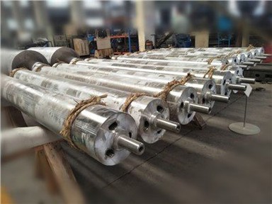
The brush roll comprises a roll body, a brush ring, a brush ring securing ring, a brush ring locking nut, and counterweights. The brush rings are mounted in groups around the roll body and are compressed at both ends by fixed rings, which are then secured by locking nuts. Due to the high rotational speed of the brush roll, dynamic balancing is crucial after installation of the brush rings. This is achieved by adding or removing counterweights and adjusting their positions to meet the G2.5 dynamic balance requirements at speeds of 750 r/min or 1500 r/min. The brush materials are typically available in two types: silicon abrasive and nylon. Additionally, the brush assembly can be of either a pressed laminated style or a wound configuration.
Brush Roll Drive:
The drive system is powered by an AC constant-speed motor. The brush roll rotates in the opposite direction to the strip flow, operating at either 750 r/min or 1500 r/min. Pressure adjustment is realized by regulating the motor-driven worm gear assembly. The worm gear converts axial motion into radial movement. Through a synchronized linkage, the worm gears located in the pedestal housing at both ends of the supporting roll maintain synchronized upward or downward movement, thereby keeping the support level with the brush roll. The motor current is adjusted proportionally to the pressure exerted by the brushes on the strip; that is, greater pressure requires higher current. This allows control of the brush cleaning force on the strip by regulating the motor current.
Support Roll and Drive
The brush roll and the support roll are arranged on the upper and lower surfaces of the strip, respectively, in an interleaved configuration. The contact between the strip and the support roll helps maintain the lateral straightness of the strip, thereby enhancing the cleaning effectiveness. Moreover, since the brush roll and the support roll do not share the same rotational axis, they should be offset by 25–30 mm to form an adequate wrap angle.
Support Roll Structure and Drive:
There are two types of support roll constructions: one with a steel surface plated with a protective layer, and the other with a rubber lining on the steel surface. Both materials see widespread application. The drive system employs VC vector control to ensure that the support roll's peripheral speed remains consistent with that of the strip.
Support Roll Adjustment:
After installation, the support roll must be returned to the strip line. To ensure that the support roll remains horizontally aligned axially, a synchronized linkage device is used. By rotating the hand wheel, the worm gear converts axial movement into radial motion. The synchronized linkage ensures that the worm gears within the pedestal housings at both ends of the support roll rise or fall simultaneously, thereby maintaining the support roll in a level condition.
Immersion Roll and Drive
The immersion roll is located at the bottom of the vertical degreasing tank, where it is responsible for effecting a 180° turn of the strip. To maintain a consistent speed with the strip, the drive employs VC vector control. The immersion roll assembly comprises the roll body, shaft, drive motor, reduction gearbox, coupling, and bearings.
Vertical electrolytic degreasing tanks occupy a smaller footprint. By allowing the strip to move vertically, they ensure a constant distance between the plates and the strip and maintain an effective degreasing action on the strip's surface, making the vertical configuration preferable over horizontal tanks. However, maintenance of vertical tanks is more challenging, particularly because the turning rolls are fully immersed in the degreasing liquid. Hence, the bearings at both ends must be equipped with rotary mechanical seals to prevent degreasing fluid leakage.
Turning Roll and Its Drive
Positioned above the vertical tank, the turning roll transitions the strip from a horizontal to a vertical orientation (or vice versa). To ensure that its speed remains consistent with that of the strip, the drive system is based on VC vector control.